 0577-5891 7200
 Online Consultation
 RichScan

Scan QR code and consult us
Off
In the fully unfolded closed position, the gate wedges in
Force down, segment stop engaged
With lower body stop block to expand gate
A tightly sealed segment is formed through two seat faces
Close to upstream and downstream seats.
Intermediate position
When operating towards the open position
The segments are wedged upward by the force of the stem
The gate is completely wedged into the gate and formed
Clearance between gate and section and seat. this
Retract the assembly so that it can slide freely
Between the surfaces of the seats.
Fully open
In the fully unfolded open position, the diversion device
The hole of the gate and the segment with
Make sure the path is clear. This will extend the segmentation
The gate is inserted into the seat to isolate the fluid from the chamber.
Fully open
In the fully unfolded closed position,
The exhaust system will release the pressure
When the body cavity overpressure.
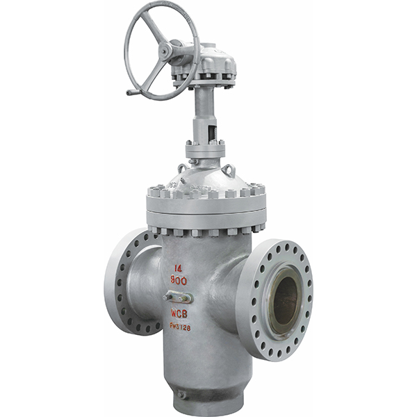
Through duct expansion gate valve
Manufactured according to API 6D.
| Structural Characteristics | Instructions |
|---|---|
| Advanced O-ring loading construction | Through its simple design and efficient performance, the two O-ring loading floating seats of the flat gate are pressure-energized. This allows for complete sealing of upstream and downstream. |
| Seat Soft and metal | O-ring loaded double O-ring design seats maintain a perfect seal with the gate in both low and high pressure applications. Soft seat inserts help ensure a primary seal at the gate. If the soft seat is damaged, the metal-to-metal seat will act as a secondary seal. |
| Double block | T When the valve is in the closed position and the pressure is equal or no pressure, the two spring-loaded seats can close the line pressure independently of the upstream and downstream pressure. This will create a two-block scene. |
| Self-relieving chamber | Dual ram and discharge plate gate designs may increase cavity pressure due to thermal expansion when in the closed position. When the cavity pressure exceeds the line pressure, the seat is forced off the gate surface, allowing excess cavity pressure to drain into the line. This allows for a balance of pressure between the body cavity and the line. |
| Metal-to-metal sealing structure | The sealing of the seat and plate adopts metal-to-metal design, which is suitable for some special working conditions, such as particle working conditions. This metal-to-metal design helps to extend the service life of the valve. |
| Secondary sealant injection system | Valves 6" and above will be equipped with secondary sealant injection fittings for stem and seat. If the seat insert or stem O-ring is damaged, seat and stem leakage can be prevented by injecting sealant into the joint. |
| Advanced Mechanical details for expansion doors | In high and low pressure applications, expansion gate valves are designed to provide a mechanical seal between the seat and gate. Expansion gate valves do not require line pressure to seal and are recommended for use when a tight mechanical seal is required. |
| Full spread close | In the full spread close position, the segment stop engages the lower body stop and the gate wedges downward to expand the gate and segment to create a tight seal to the upstream and downstream seats. Body cavity exhaust will help provide tight closure. |
| Intermediate position | When operated towards the open position, the gate passes through the wedge Angle of the sector segment. This retracts the assembly, allowing it to slide freely between the seat surfaces. |
| Fully unfolded open | In the fully unfolded open position, the sector stop engages the upper body stop and the gate wedges upward. This extends the segments and gates into the seat, thereby isolating the fluid from the cavity. |